This is a test of the "site alert message system". (edited)
Ceramic Vacuum Breaks and Isolators

Electrical Breaks / Isolators
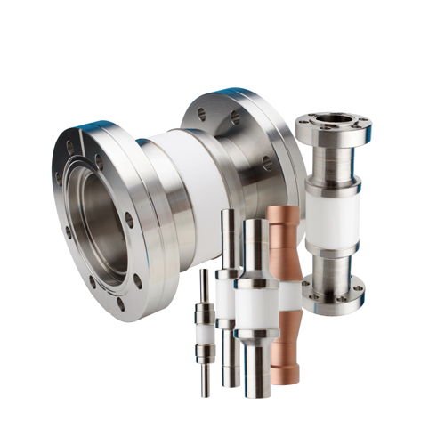
Accu-Glass Products, Inc. offers a complete line of tubular electrical breaks for vacuum applications requiring cryogenic, water and/or vacuum transmission lines. Cryogenic and vacuum breaks consist of ceramic insulating tubes with metal tubes brazed to each end and welded to either Conflat® compatible CF flanges or standard ISO KF flanges. Water breaks consist of ceramic tubes brazed to copper tubes that can be easily brazed to existing copper water supply-lines. The central ceramic tube provides electrical isolation between the conductive metal ends. If the breaks are used between two rigid components, a bellows should be used in the system to reduce mechanical stress that may cause the ceramic to break. Accu-Glass Products’ electrical breaks are all suitable for service in ultrahigh vacuum environments. Cryogenic and vacuum breaks are not suitable for water service because of corrosion, while water and vacuum breaks are not suitable for cryogenic service because of expansion differentials and material embrittlement.

Features
- Vacuum, water and cryogenic types
- Low temperature service to -200°C (Cryogenic)
- High temperature service to 400°C (450°C short term)
- Alumina ceramic electrical insulator
- Custom solutions on request
Specifications
| Electrical 1 | |
| Voltage, Vacuum Break | 5~35kV |
| Voltage, Water Break | 5kV |
| Voltage, Cryogenic Break | 5 and 10kV |
| Material | |
| Tube, Vacuum and Cryogenic Break | 304 Stainless Steel |
| Tube, Water Break | Copper |
| Insulator, All Breaks | Alumina |
| Vacuum Range | |
| UHV, Ultrahigh Vacuum | 1x10⁻¹⁰ Torr |
| HV, High Vacuum | 1x10⁻⁸ Torr |
| Temperature Range 2, 3 | |
| Vacuum Break | |
| CF Flange | -55° to 450°C |
| ISO Flange | -25° to 200°C |
| Water Break 4 | 0° to 100°C |
| Cryogenic Break | -200° to 400°C |
| Thermal Gradient, Maximum | 25°C / Minute |
| Notes |
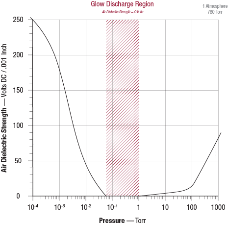
- Electrical ratings are maximum test values, with break's vacuum side at ≤ 1x10⁻⁴ Torr. Also, see 'glow discharge' graph for variation of air dielectric strength vs pressure.
- Overall assembly ratings must be adjusted to that of its lowest rated component.
- Ceramic-to-metal assemblies subjected to sudden and/or repeated thermal shock will have shorter life spans. For optimum product life, heating and cooling must always be performed gradually, and within specified thermal gradient limits.
- Water breaks have been designed for use with properly grounded, closed-loop cooling systems that use deionized water and/or other non-conductive coolants.


